

The Interfaces visualization shows a single system and all interfaces in which it acts as sender or receiver, as a flow diagram.
Purpose: Understand the integration dependencies of one system: which systems send data to it, which systems it sends data to and through which interfaces.
Navigate to Reporting → Landscape → Visualization → by System → Interfaces to open the visualization.
System Selection
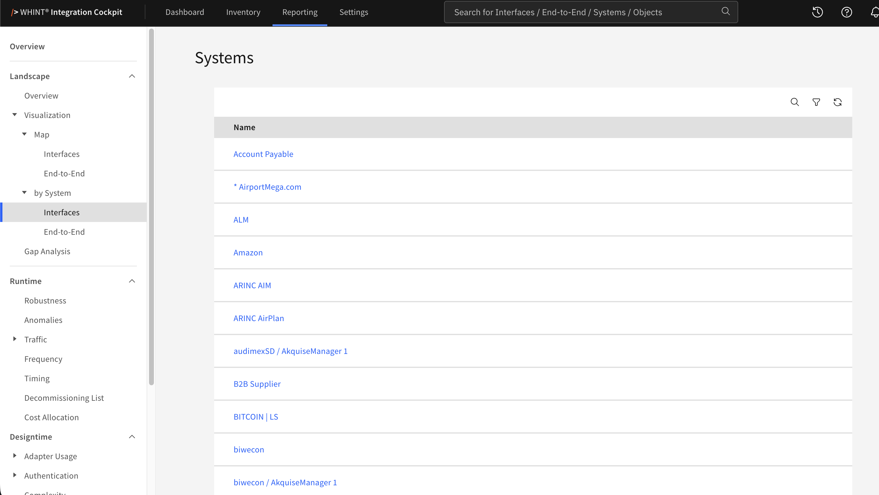
The list shows the harmonized system names. Select a system to open its visualization.
The list includes systems that participate in at least one interface with both a sender and receiver assigned. A system whose interfaces have no counterpart assigned is therefore not listed.
Use the magnifier to search by name and description and the funnel icon to filter by Data Source and Environment. The list opens with Production selected.
Alternatively, open the visualization for a single system directly from Inventory → Landscape → Systems using Visualization → Interfaces on the system details.
System Visualization
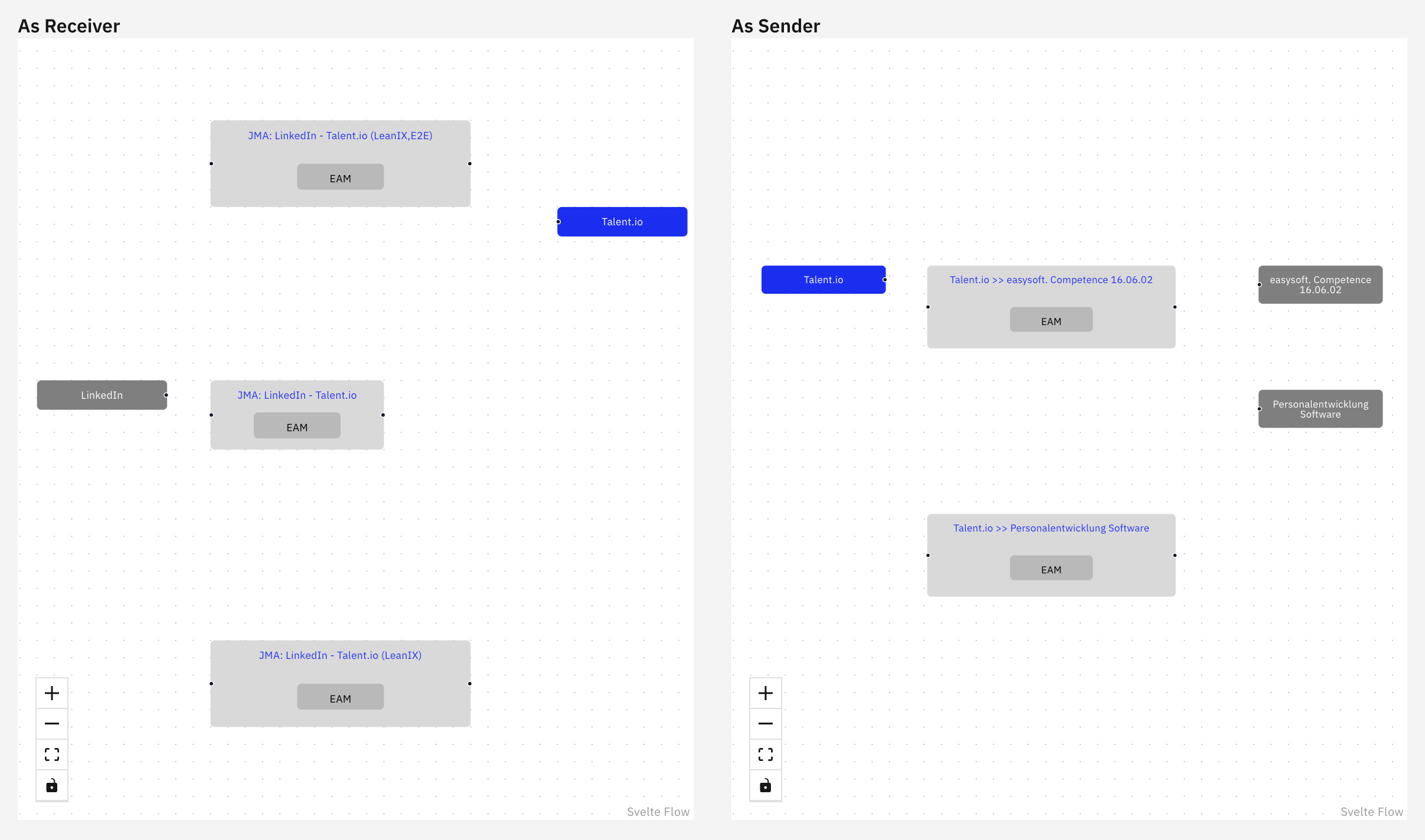
The diagram is shown in up to two sections:
-
As Receiver — Interfaces in which the selected system receives data. The sending system is on the left, and the selected system is on the right
-
As Sender — Interfaces in which the selected system sends data. The selected system is on the left, and the receiving system is on the right
A section is only displayed when the system has interfaces in that direction. A system that only sends data therefore shows As Sender alone.
What you see:
-
Blue node — The selected system
-
Grey box — One interface. The label inside the box shows the interface type
-
Grey node — The system on the other side of the interface
Read each row from left to right: the sending system, the interface that carries the data, and the receiving system.
Each interface is drawn as its own box, so a system pair connected through several interfaces appears once per interface.
Click an element to open its details in the Inventory:
|
Element |
Opens |
|---|---|
|
System node |
The system details under Inventory → Landscape → Systems |
|
Interface box |
The interface details under Inventory → Interfaces |
The diagram opens with the environment selected in the system list. Use the Data Source and Environment filters in the top right to change the scope, the diagram is rebuilt as soon as a filter is changed.
The controls in the lower left corner allow you to:
-
Plus button (+): Zoom in for detailed view of integration flow containers and component relationships
-
Minus button (-): Zoom out for broader end-to-end process overview
-
Fit view button (□): Single click to automatically adjust view to show all integration flows perfectly
-
Lock button: Lock the view to prevent accidental zooming or moving while analyzing complex flows
Related Documentation
-
Reporting → Landscape → Visualization → by System → End-to-End — View the same system based on End-to-End integrations
-
Reporting → Landscape → Visualization → Map → Interfaces — View all systems and their interfaces in one map
-
Reporting → Landscape → Overview — View the landscape counts behind the visualization
-
Inventory → Interfaces — Open the interface details shown in the diagram
-
Inventory → Landscape → Systems — Open the system details shown in the diagram
-
Settings → Transformation Rules — Configure system harmonization
Last Updated: September 21, 2026